
Porosity is one of the most common quality problems in high-pressure die casting (HPDC). It may not be visible on the as-cast surface, but it can appear during CNC machining, leak testing, or pressure testing—and by that stage, the cost of the defect is already much higher.
For pressure-tight components such as valve bodies, pump housings, hydraulic components, and pneumatic parts, even a relatively small internal void can become a functional problem. A pore exposed on a sealing surface can cause leakage, while defects hidden below the machining allowance can turn an apparently good casting into a rejected part.
Porosity is rarely caused by a single process parameter. In practice, it is the result of several factors working together.
Some are determined before production begins:
- Gating and venting design
- Overflow and vacuum arrangements
- Molten metal quality
Others are controlled during production:
- Plunger lubrication
- High-speed injection velocity
- High-speed switch point
- Die temperature
This article brings these factors together into a practical porosity-control framework. The numerical process data discussed in the four parameter sections below are based on a referenced die-casting process trial. They should be treated as trial-specific observations rather than universal settings for every HPDC application.
Why Porosity Matters to OEM Buyers
Porosity is not simply a cosmetic casting defect. For an OEM buyer, it can affect three areas that directly influence project cost and reliability.
1. Pressure Tightness
Valve bodies, hydraulic components, pneumatic parts, and similar products may require pressure-tight sealing surfaces.
A pore that is invisible on the casting surface may become a through-hole after machining. If it opens onto a sealing surface, the component may fail a leak test even though its external appearance is acceptable.
2. Machining Yield
Internal defects often become visible only after material is removed.
For example, a pore located just below the machining allowance may remain completely hidden during incoming inspection. Once a CNC operation reaches that area, the defect is exposed and the casting becomes scrap.
This is why evaluating casting quality only from the as-cast appearance can be misleading.
3. Long-Term Reliability
The location, size, and distribution of internal defects matter.
Porosity in a non-critical structural area may have little practical effect. The same defect near a sealing surface, highly stressed section, or fatigue-sensitive area can be much more serious.
For this reason, porosity acceptance should be related to the function of the component, rather than applying the same inspection rule to every casting.
Six Critical Factors for Controlling Porosity in HPDC
1. Gating and Venting Design: The Foundation of Porosity Control
Porosity control starts with the die.
Once a die is manufactured, changing the fundamental flow pattern or venting strategy can become expensive and time-consuming. That is why gating and venting should be reviewed during the engineering stage, before tooling is released.
Gating System The gating system controls how molten aluminum enters and fills the cavity.
Poor gating design can create several problems:
- Excessive turbulence and air entrapment
- Uncontrolled filling sequences
- Air pockets in isolated areas
- Inadequate feeding and pressure transmission
- Localized solidification before the cavity is completely filled
A practical design objective is to maintain a controlled and predictable metal flow. Sudden changes in flow direction, unnecessary restrictions, and poorly positioned gates can increase turbulence and make air evacuation more difficult.
Gate location should also be considered together with the venting strategy. The metal should be able to push air toward the intended venting and overflow areas rather than trapping it inside the casting.
Venting and Overflow During high-speed filling, the cavity contains air as well as gases generated by release agents and other process materials. These gases need an effective path out of the die.
Important considerations include:
- Adequate venting area
- Vent locations at the end of filling
- Proper overflow placement
- Clear evacuation paths
- Maintenance of vents throughout production
Overflow pockets can serve more than one purpose. They can collect cold metal and oxides while also helping move trapped air toward the venting system.
For highly porosity-sensitive components, vacuum-assisted die casting can be considered. Removing a significant portion of the air from the cavity before filling can reduce gas-related defects, although the additional equipment, tooling complexity, and maintenance requirements need to be justified by the product requirements.
Why This Matters A process engineer can adjust injection speed, die temperature, or lubrication, but these adjustments cannot completely compensate for a fundamentally poor filling and venting design.
That is why porosity control should begin with DFM and die-flow analysis, not with production troubleshooting.
2. Molten Aluminum Quality: The Hidden Variable
Even a well-designed die can produce porous castings if the molten metal is not properly controlled.
Hydrogen and oxide inclusions are two important concerns in aluminum melt quality. Hydrogen has much higher solubility in liquid aluminum than in solid aluminum, so gas can come out of solution during solidification and contribute to porosity.
Melting and Holding Conditions Melting temperature, holding temperature, holding time, furnace condition, and exposure to moisture all influence melt quality.
For common die-casting alloys such as ADC12, a melt temperature in the general range of approximately 640–680°C may be used as a practical reference. However, the actual process window should be established according to the alloy specification, furnace system, production cycle, and casting requirements.
The same principle applies to holding time. There is no single holding-time limit that is suitable for every foundry. Longer exposure at elevated temperature can increase oxidation and hydrogen pickup, so the process should be controlled rather than allowing molten metal to remain in the furnace unnecessarily.
Degassing and Melt Treatment Rotary degassing is commonly used to reduce dissolved hydrogen in aluminum melt.
An impeller disperses nitrogen or argon into the molten metal. The fine bubbles provide a path for dissolved hydrogen to leave the melt, after which the gas and floating inclusions can be removed from the surface.
Depending on the alloy and process, additional melt-cleaning or refining procedures may also be used.
The important point for OEM buyers is not simply whether a supplier says that it performs “degassing.” The process should be controlled and verifiable.
For porosity-sensitive castings, useful controls may include:
- Defined melt-temperature limits
- Controlled holding time
- Degassing procedures
- Hydrogen testing where required
- Melt cleanliness monitoring
- Defined furnace and ladle management procedures
A casting process cannot reliably compensate for poor melt quality. If excessive gas is already present in the aluminum, optimizing machine parameters alone will not solve the problem.
3. Plunger Lubrication: A Small Process Detail with a Big Effect
Plunger lubrication is necessary to reduce friction and wear between the plunger tip and shot sleeve.
The problem begins when lubrication is excessive.
During high-speed injection, excessive lubricant can decompose or vaporize and become another source of gas inside the shot sleeve. If that gas is carried into the cavity with the metal, it can contribute to gas-related porosity.
What the Trial Data Showed In the referenced process trial, two plunger lubrication settings were compared.
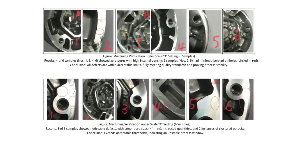
| Lubrication Setting | Biscuit Appearance | Machined Porosity Observation |
|---|---|---|
| Setting 3 | Silver-colored metallic appearance with very few dark areas | No severe defects; most samples showed no visible pinholes, while some showed only very small pores below 0.4 mm |
| Setting 4 | Significantly darker, with a burnt or carbonized appearance | Dense pores larger than 1.0 mm were observed around the gate area after machining |
The important lesson is not that “setting 3” should be copied to another machine. Plunger systems, shot sleeves, lubricants, and machine settings vary.
The useful lesson is that lubrication should be kept at the minimum effective level, and the condition of the biscuit can provide a simple process-monitoring signal.
If the biscuit consistently becomes excessively dark or shows obvious burning, the lubrication quantity and application method should be reviewed.
For production control, this is a relatively simple check that should not be overlooked.
4. High-Speed Injection Velocity: Finding the Right Process Window
Injection velocity is one of the most influential HPDC parameters because it affects filling time, metal temperature, turbulence, and air entrapment.
Too slow, and the metal may lose too much heat before filling the cavity.
Too fast, and excessive turbulence can increase air entrapment.
The objective is not to use the highest possible speed. It is to find a stable process window for the specific die and casting.
Referenced Trial Results In the referenced trial, six high-speed injection velocities were evaluated: 2.4, 2.6, 2.8, 3.0, 3.2, and 3.4 m/s.
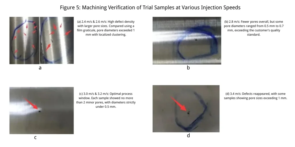
| High-Speed Velocity | Observed Result | Trial Assessment |
|---|---|---|
| 2.4–2.6 m/s | Dense pinhole defects; some pores exceeded 1.0 mm | Unsatisfactory |
| 2.8 m/s | Fewer defects, but pores of approximately 0.5–0.7 mm remained | Marginal |
| 3.0–3.2 m/s | Good internal density; no more than two small pinholes per section in the trial, with defects below 0.5 mm | Best-performing window in the trial |
| 3.4 m/s | Larger voids reappeared, with pores exceeding 1.0 mm | Unsatisfactory |
The trial therefore identified 3.0–3.2 m/s as the best-performing window under those specific test conditions.
This should not be interpreted as a universal injection-speed specification.
Actual injection velocity must be developed around the complete casting system, including:
- Part geometry
- Wall thickness
- Gate design
- Shot sleeve dimensions
- Alloy
- Metal temperature
- Die temperature
- Required filling time
- Machine characteristics
A good process engineer does not ask, “What injection speed is correct for aluminum die casting?”
The better question is: What injection-speed window gives this particular casting a stable filling pattern and acceptable internal quality?
5. High-Speed Switch Point: Controlling the Transition into Fast Filling
The high-speed switch point determines when the plunger changes from the low-speed stage to the high-speed filling stage.
This setting is closely related to filling time and metal temperature.
If the switch occurs too late, the metal spends more time in the relatively cool shot sleeve before high-speed injection begins. Excessive heat loss can increase the risk of premature solidification and incomplete or unstable filling.
Referenced Trial Results Three switch-point positions were evaluated in the referenced trial: 360 mm, 370 mm, and 380 mm.
| Switch Point | Machining Observation | Trial Result |
|---|---|---|
| 360 mm | Only one of eight samples showed a minor approximately 0.4 mm pinhole on the machined section | Best result |
| 370 mm | Up to approximately 0.8 mm pores were observed; some samples contained several defects | Increased defect risk |
| 380 mm | Severe pores exceeding 1.0 mm appeared on multiple machined surfaces | Poor result |
In this trial, 360 mm produced the best result.
Again, this is a process-specific finding, not a universal machine setting. The reason for the trend is more important than the number itself.
A delayed switch point extends the low-speed stage. The aluminum melt remains in the shot sleeve for longer, loses heat, and may begin to form a partially solidified layer before the high-speed stage starts.
Once the material has lost too much fluidity, later pressure and velocity increases cannot fully recover the original filling conditions.
This is why switch-point adjustment should be evaluated together with injection velocity, shot profile, metal temperature, and die temperature.
6. Die Temperature: One of the Most Easily Overlooked Variables
Die temperature has a direct influence on metal flow, filling behavior, solidification, and defect formation.
A die that is too cold can cause the aluminum melt to lose heat rapidly when it contacts the cavity surface. This can lead to premature solidification and make it more difficult for the metal to fill and vent the cavity properly.
Referenced Trial Results In the referenced trial, die surface temperatures were compared in two ranges:
- Below 160°C
- 160–224°C
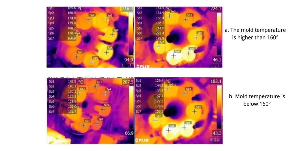
| Die Surface Temperature | Observed Result |
|---|---|
| Below 160°C | All machined samples in the trial showed severe pinhole defects, with defects larger than 1.0 mm |
| 160–224°C | Defects were reduced substantially; machined sections showed no more than two pinholes, with maximum pore size below approximately 0.4 mm |
The important qualification is that these results come from the referenced trial. They do not mean that every aluminum die casting must operate above 160°C.
The appropriate die-temperature range depends on the alloy, casting geometry, cycle time, cooling-channel design, and process requirements.
What the trial demonstrates is the importance of maintaining a stable die-temperature window rather than allowing the die to run excessively cold.
For production, die-temperature control can be supported by:
- Die temperature monitoring
- Thermocouples where appropriate
- Thermal imaging during process validation
- Controlled die heating
- Proper cooling-channel design
- Monitoring of temperature stability during continuous production
For porosity-sensitive components, temperature stability is often more important than simply reaching a target temperature once during setup.
A Practical Porosity-Control Checklist for OEM Projects
The six factors can be divided into two stages: engineering controls before production and process controls during production.
| Stage | Factor | Key Control | Typical Verification |
|---|---|---|---|
| Engineering | Gating & Venting | Controlled filling, adequate venting, proper overflow placement | DFM review, filling simulation, T1 inspection |
| Engineering | Material | Melt quality (temperature, holding time, degassing) | Melt records, hydrogen testing where required |
| Production | Plunger Lubrication | Minimum effective lubrication | Biscuit appearance and process records |
| Production | Injection Velocity | Stable velocity window for the specific casting | Machine shot-profile monitoring |
| Production | Switch Point | Proper transition from low-speed to high-speed injection | Machine parameter records and trial validation |
| Production | Die Temperature | Stable temperature within the validated process window | Thermocouples, thermal imaging, die-temperature monitoring |
This checklist is more useful than treating any single parameter as a universal recipe. Porosity control works best when the parameters are considered as a system.
How Should OEM Buyers Verify Porosity?
One of the most important points is that there is no single inspection method that can answer every porosity question. The appropriate inspection method depends on the component’s function and risk.
- Visual Inspection: Useful for detecting obvious surface defects, but insufficient for evaluating internal porosity.
- Machining Inspection: Particularly important for components with critical sealing surfaces because internal pores can become exposed only after material removal.
- X-Ray Inspection: Provides a non-destructive method for evaluating internal defects and is especially useful during tooling validation or process qualification. However, inspection criteria should be defined in advance.
- Leak Testing: For pressure-tight components, leak testing may be more directly related to the product’s actual function.
What Should Be Defined Before Production?
For a porosity-sensitive die-casting project, OEM buyers should clarify the following before tooling and mass production:
- Which areas are functionally critical?
- Which surfaces will be machined?
- Are there pressure-tight or sealing requirements?
- Is internal porosity inspection required?
- Is X-ray inspection required during qualification or production?
- Is leak testing required?
- What pore size is acceptable?
- Are there restrictions on pore location?
- What machining allowance will remain above critical areas?
- What documentation should the supplier provide?
These questions are often more important than simply asking a supplier for the lowest casting price. A supplier may be able to produce a visually excellent casting that does not meet the internal quality requirements of a pressure-tight component. The quality specification needs to be established before production, not after the first batch fails leak testing.
How RuiYu Approaches Porosity-Sensitive Die Casting
At RuiYu, we do not treat porosity as a final-inspection problem alone. For projects where internal density is important, the risk needs to be considered from the engineering stage through production and final validation.
Our approach typically includes:
Before Tooling:
- Review part geometry and critical functional areas
- Evaluate gating, venting, and overflow concepts
- Identify areas with higher porosity risk
- Review machining allowances around sealing surfaces
- Coordinate tooling design and process requirements
During Process Development:
- Establish the appropriate injection-speed and switch-point window
- Review die-temperature requirements
- Monitor plunger lubrication
- Coordinate molten-metal quality controls
- Validate the process through machining and, where required, X-ray or leak testing
During Production: Production quality is monitored through the manufacturing partners involved in the project, with process requirements and inspection criteria established according to the component’s function.
This is particularly important for projects where the casting will later be CNC machined, pressure tested, or assembled into a larger functional product. The goal is not to add inspection simply for the sake of inspection. The goal is to control the right risks at the right stage.
Conclusion
Porosity in aluminum die casting is rarely solved by adjusting one machine parameter.
The most reliable approach is to control the entire process: Die Design → Melt Quality → Plunger Lubrication → Injection Velocity → Switch Point → Die Temperature → Validation
The referenced process trials show how strongly individual parameters can affect internal casting quality. At the same time, the actual numerical values should always be treated as process-development data for a specific casting system, not as universal HPDC standards.
For OEM buyers, the more important question is not simply: “Can your factory make this casting?” It is: “How will you control internal quality, and how will you prove that the process meets the functional requirements of my part?”
That question changes the discussion from unit price to process capability, quality risk, and total project cost.
If you are sourcing a porosity-sensitive aluminum die-cast component, such as a valve body, pump housing, hydraulic component, motor housing, or other pressure-related part, RuiYu can help review the project from the engineering and supply-chain perspective.
Send us your 3D CAD file (STEP/IGES) and, if available, your current defect or rejection data. We can review the part structure, identify potential porosity risks, and discuss suitable tooling, process-control, and inspection approaches with our manufacturing partners.
