
High-pressure die casting is widely used for lightweight automotive components, but some casting geometries create significant challenges for mold life and sealing performance.
A typical example is a closed-form aluminum automotive cover with an integrated sealing groove. With conventional peripheral gating, the molten aluminum directly impacts the sealing-groove area during every shot. Over time, this localized erosion can cause premature mold cracking and transfer defects onto the casting surface.
In this engineering case, we developed a three-plate die casting mold with a double-center feeding structure for a V8 engine chain cover shell. By changing the feeding position and optimizing the mold structure, the solution significantly reduced localized mold erosion and improved both mold life and casting quality.
1. Part Overview and Engineering Challenge
The component evaluated in this project was a V8 engine chain cover shell manufactured from A380 aluminum alloy.
| Item | Specification |
|---|---|
| Material | A380 Aluminum Alloy |
| Density | 2.75 g/cm³ |
| Overall Dimensions | 305.059 × 243.811 × 88.683 mm |
| Part Weight | 0.83 kg |
| Part Volume | 309 cm³ |
| Surface Area | 856.03 cm² |
| Basic Wall Thickness | ≥ 2.1 mm |
| Casting Shrinkage | 0.55% |
The component has a relatively flat, closed-form structure with an integrated sealing groove. Because the sealing groove directly affects the sealing performance of the finished component, the surface quality and dimensional stability of this area are particularly important.
The Original Failure Mechanism
With the conventional gating arrangement, the inner gate directed molten aluminum toward the sealing-groove area.
The repeated high-speed flow of molten aluminum caused severe localized erosion and thermal loading on the corresponding mold area. As production continued, cracks could develop in the vulnerable section of the mold.
Once the mold surface deteriorated, raised defects could be transferred directly to the sealing area of the casting.
For a component with a sealing function, this is more than a cosmetic defect. Surface damage in this area can affect the installation and sealing performance of the final assembly.
The key engineering question was therefore not simply how to repair the damaged area, but how to move the metal flow away from the sealing groove in the first place.
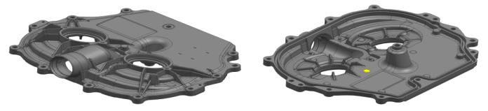
Figure 1 — 3D Drawing of the V8 Engine Chain Cover
2. Why the Conventional Gating Structure Was Not Suitable
The initial mold design used a conventional peripheral feeding arrangement.
This approach is commonly used for cover-type die castings, but the geometry of this particular component created a problem: regardless of which peripheral location was selected for the gate, the metal flow still had to pass through or close to the critical sealing-groove region.
The result was concentrated erosion at the same mold location.
A conventional response would be to use a mold insert structure, allowing the damaged section to be replaced separately. This can extend maintenance intervals, but it does not eliminate the underlying cause of the erosion.
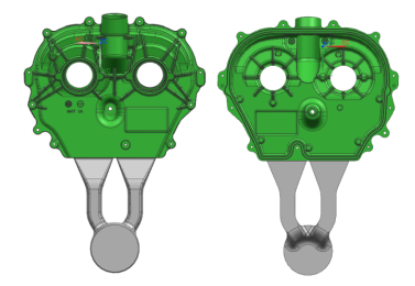
Figure 2 — Conventional Gating Design
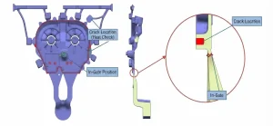
Figure 3 — Die-Casting Mold Failure Location
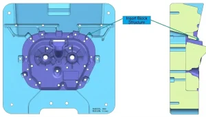
Figure 4 — Mold Insert Structure for the Vulnerable Area
For this project, we therefore looked for a different solution:
Instead of making the vulnerable mold section easier to replace, could the gating system be redesigned so that the vulnerable area was no longer directly exposed to the metal flow?
This became the basis for the new mold concept.
3. Double-Center Feeding: The Key Design Change
After reviewing the casting geometry, we found that the most practical feeding locations were the two central openings of the component.
The overall casting has a relatively round, disk-like geometry, while the internal ribs extend radially from the central area.
This geometry provides a natural pathway for a centralized feeding strategy.
Based on this observation, we developed a three-plate die casting mold with double-center feeding.
The new design moved the primary feeding locations away from the sealing groove and used the central structural geometry of the casting to distribute molten aluminum through the component.
The redesigned structure also provided advantages for:
- Metal flow distribution
- Mold erosion control
- Exhaust and venting
- Structural support of the mold
- Protection of the sealing-groove area

Figure 5 — Double-Center Gating Three-Plate Die Casting Mold Design
The double-center gating layout moves the primary metal-flow paths away from the critical sealing-groove area while making use of the radial rib structure of the casting.
4. Three-Plate Mold Structure
The feeding redesign required a corresponding change to the mold structure.
Instead of using a conventional two-plate configuration, the new tooling adopted a three-plate mold structure.
The additional plate allowed the feeding and gating system to be arranged around the two central feeding locations while maintaining appropriate mold opening, clamping, and positioning functions.
The mold structure was optimized in several areas.
H13 Tool Steel
The mold was manufactured using H13 tool steel, heat-treated to approximately HRC 44–46.
H13 was selected to provide the required combination of hot-strength, thermal-fatigue resistance, and wear resistance for high-pressure aluminum die casting.
Anti-Soldering Geometry
The relevant cutting edges were designed with approximately a 45° angle to reduce the tendency of aluminum to stick or solder to the mold surface.
This is particularly important in areas exposed to repeated high-temperature aluminum flow.
Elastic Clamping Structure
An elastic clamping device with a clamping force of approximately 40 kN was incorporated into the mold structure.
Its purpose was to help prevent premature separation between the moving template and the fixed mold moving plate during operation.
Precision Mold Alignment
The guide pillars, templates, and related mold components were manufactured and matched to maintain accurate alignment.
The fixed mold fixed plate, fixed mold moving plate, and moving template were fitted together as a complete system.
During manual mold testing, the moving plate was checked for smooth movement. There should be no obvious jamming or abnormal resistance during the push test.
Proper lubrication and uniform application of mold-clamping oil were also required to maintain smooth operation.

Figure 6 — Three-Plate Die Casting Mold Structure
5. Conventional Two-Plate Mold vs. Optimized Three-Plate Mold
The new mold structure was evaluated against the original production arrangement.
| Performance Metric | Conventional Two-Plate Mold | Optimized Three-Plate Mold |
|---|---|---|
| Die Casting Machine | DCC900T | DCC800T |
| Mold Life | 60,000 shots | 100,000 shots |
| Casting Defect Rate | 9.2% | 2.2% |
| Production Cycle | 65 s | 68 s |
What the Results Show
The most significant improvement was mold life.
Mold life increased from approximately 60,000 shots to 100,000 shots, reducing the frequency of major mold maintenance and replacement.
At the same time, the casting defect rate decreased from 9.2% to 2.2%.
The production cycle increased slightly, from 65 seconds to 68 seconds. In this application, the additional cycle time was accepted in exchange for improved mold durability and more stable casting quality.
The machine requirement also changed from a DCC900T to a DCC800T configuration, providing a smaller machine option for the optimized tooling arrangement.
6. Why the New Feeding Structure Improved Mold Performance
The main improvement did not come from simply adding another mold plate.
The critical change was the relationship between the feeding position and the casting geometry.
In the original configuration, molten aluminum repeatedly attacked the mold section around the sealing groove.
In the redesigned configuration, the feeding points were moved toward the central openings of the casting.
This changed the metal-flow path and reduced direct erosion of the critical sealing-groove area.
The radial rib structure of the casting also helped distribute the incoming metal toward the surrounding areas.
As a result, the new design achieved three important objectives:
1. Reduced localized mold erosion
The sealing-groove area was no longer the primary target of the incoming metal flow.
2. Improved casting surface quality
Reducing mold damage also reduced the transfer of raised defects from the mold onto the casting.
3. Extended mold service life
The reduction in localized erosion allowed the mold to remain in production for significantly more shots before major maintenance was required.
7. Engineering Takeaway
This case demonstrates an important principle in die casting mold design:
When a mold repeatedly fails at the same location, replacing the damaged insert may solve the maintenance problem, but redesigning the metal-flow path can solve the underlying engineering problem.
For closed-form aluminum components with critical sealing surfaces, the gating system should therefore be evaluated together with:
- Casting geometry
- Sealing-groove location
- Metal-flow direction
- Local mold erosion
- Venting requirements
- Mold opening and clamping structure
- Expected production volume
The most suitable gating solution is not always the simplest or most conventional one. In some cases, the geometry of the casting itself provides the best opportunity for a different feeding strategy.
Conclusion
For this V8 engine chain cover shell, the original peripheral feeding arrangement created concentrated erosion around the sealing groove and limited mold durability.
By redesigning the tooling as a three-plate die casting mold with double-center feeding, the metal-flow path was moved away from the critical sealing area while taking advantage of the casting’s central openings and radial rib structure.
Production testing showed:
- Mold life increased from 60,000 to 100,000 shots
- Casting defect rate decreased from 9.2% to 2.2%
- Production cycle increased only slightly from 65 s to 68 s
- Machine requirement changed from DCC900T to DCC800T
The project illustrates how gating design, mold structure, and casting geometry must be considered together when solving difficult high-pressure die casting problems.
For OEM projects involving complex aluminum housings, covers, and structural components, early DFM and mold-flow evaluation can help identify potential erosion, filling, venting, and tool-life issues before the mold is manufactured.

